A couple of weeks ago I wrote a post covering an introduction to dodging. It outlines typical radiometric problems, introduced the concept of dodging, and then went into statistics generation.
Today I will focus on the actual dodging process. For the example data I will use some frame camera imagery covering Laguna Beach, California (from the LPS Example Data).
Here's a screen capture of the original undodged imagery:
It is apparent that the radiometry is uneven. In particular, the bottom right quarter of the image has a whitish hue. You can see that the hills should be the same color as the rest of the scene, but instead they are discolored and uneven throughout. In addition, there are several radiometrically inconsistent areas throughout the image. For example the urban area on the bottom-left looks completely washed out (lacking contrast), as is the area under development just above it.
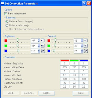
After generating statistics (discussed in the previous post), the next step involves adjusting the correction parameters. After statistics describing the imagery have been generated, the dodging algorithm applies a "target" output value for each pixel. For example, the input DN value of one specific pixel band may be 125. After statistics are generated (describing the image or a group of images), the dodging process identifies a target "adjusted" pixel DN value. Then, constraints are used so that extreme changes to the imagery are not applied. Here are the ImageEqualizer constraints and correction parameters for the Laguna image above:
- Band Independent: if checked, allows you to adjust bands independently. This is useful if your imagery is skewed in one band (e.g. your imagery has a "reddish" hue and you want to align the red band with the green and blue bands).
- The balancing options allow you to adjust the images individually or as a group. This is a useful option if you are adjusting images that have radiometric differences across the images. For example, if you have flight lines that were flown on different days with different lighting conditions you would definitely want to balance across images to even up the radiometry (if the final product is an orthomosaic).
- The brightness and contrasts sliders are relatively self-explanatory. You can adjust them for each band. The "undo" button will take you back to the default brightness/contrast value.
- The constraints section allows for control over how the dodging algorithm is applied to an image or group of images. It comes with pre-defined defaults (which you can see above). These parameters are critical for tweaking the image adjustments.
 The original image is on the left and the dodged image is on the right. You can see that a lot of the problems in the original image have been resolved. However, by adjusting the parameters it can still be improved. The contrast is still fairly low, and the light area on the bottom right is still noticeable (although much less so).
In an attempt to improve it even more, I adjusted two of the constraint parameters. These were the "Maximum Contrast" and "Maximum Grey Shift" parameters - which are two highly critical constraints in any dodging process. The max contrast constraint has a default value of 1.3, which attempts to limit excessive contrast adjustment in low contrast areas. Increasing this value will bump up the limits on "target" contrast adjustments. Since the input imagery has some low-contrast areas, I bumped this constraint up to 1.8. Maximum Grey Shift applies a limit, by default 32, on how much a pixel's DN value can shift. For example, a specific pixel may have a DN value of 120 in one band. The dodging algorithm may determine that the "target" value should be 160 (e.g. it needs a pretty big adjustment). This constraint with the default 32 value will limit the final adjustment to 152. The reason for this is to limit extreme changes in the imagery. Since I could still see at least minor unevenness in the radiometry with the default constraints, I increased the max grey shift to 50.
Here is a screenshot previewing the original and dodged image (left) with my final dodging parameters (right).
 In addition to changing the constraints outlined above, I also decreased the brightness a bit and bumped up the contrast (evenly across bands - I didn't adjust any single band more than another). This helped to reduce the washed out effect and produce an even scene.
Here's a close up of the urban area with a part of it under construction. You can see how the dodged image on the right has much better results. Grassy areas are green, roofs look correct, and the construction site doesn't look so washed out.

I used ImageEqualizer for dodging this example image, but the same dodging algorithm is also embedded as a color correction option in ERDAS MosaicPro. Applying dodging in MosaicPro will apply the results to the output Mosaic and will not impact the input images. This can be handy for "two-stage" dodging. For difficult radiometry, it is sometimes necessary to dodge the imagery twice: once right after scanning and once during (or after) the photogrammetric processing (e.g. during or after mosiacking).

No comments:
Post a Comment