Tuesday, October 20, 2009

Softcopy Photogrammetry Pricing

It's rare to see any publicity at all around photogrammetry software pricing, so I was surprised to see this post from the All Points Blog:


"I saw a quick demo of Intergraph’s ImageStation which provides image analysts the ability to view in stereo. Intergraph has provided a solution for softcopy photogrammetry for many years. What is different however is the price point. The combination of stereo glasses, a video card using OpenGL technology, a single high-resolution monitor and software will cost under $10K. In the early days of Intergraph's Z/I Imaging softcopy photogrammetry solutions, the price exceeded $100K."

In general I think there has been a downward pricing trend over the past several years, but I also suspect that all the major vendors have "modular" pricing. I doubt the $10K price quoted above would be a full seat (e.g. full range of capabilities) of ImageStation - but if it does it would certainly be a competitive price... It will be interesting to see if and how pricing models evolve as various vendors (hopefully) shift away legacy desktop systems to SaaS and other approaches.

Friday, October 16, 2009

Thoughts on Google Building Maker and 3D Building Extraction

Earlier this week Google introduced the Google Building Maker, which it bills as a simple tool for creating buildings for Google Earth. I gave it a whirl earlier today and while it is a relatively simple toolset, the direction is impressive and has some broad-reaching implications for the future.


The Concept
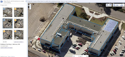
The general concept is fairly straightforward: using nothing but a browser, you can create a digital 3D representation of building structures using a very basic set of tools. Target buildings are located from a top-down view, and then buildings can be digitized from a series of oblique photos. Several oblique photos can be used to ensure your measurements are accurate from various angles. When you're finished digitizing your target building, you can save it to the Google 3D Warehouse. Upon saving, textures from the various photos are automatically applied to the model. Once the model is uploaded to the 3D Warehouse, you may download it as a KMZ or Collada file.

The Workflow
1) The first step is to launch the Google Building Maker.

2) Once the Building Maker is launched, you have to select a city to extract a model from. At present there are a few dozen cities in the USA, Canada, Mexico, Europe and Japan available. Why can't you extract buildings from your hometown? Most likely because the entire system relies on oblique aerial (not satellite) photography for making 3D measurements. The reason more cities aren't available is because oblique aerial photography is not cheap to acquire: so it makes sense that the currently available cities are clustered in the more prosperous regions of the world. Think hyperlocal advertising...

3) Once you've chosen a city, you are provided with the ability to zoom into a location until you can see a placemark. Once you're at the right zoom level, you can select/drag/drop the placemark to choose the building you wish to model. One interesting aspect of this process is that, in the initial view, you are provided with a color coded graphic overlay of the particular city you want to create a model in. The blue area, typically in the urban core, shows where buildings already exist. The white area shows the areas where Google doesn't have 3D buildings but does have all the ingredients (read: oblique photography) to create them.

Legend: Blue = Buildings Already Exist, White: No Buildings


Selecting an individual building

4) After you have dropped a placemark on a building, hit the "Start Building" button on the left. This will switch your perspective from a top-down imagery view to an oblique perspective view. You'll also notice a series of modeling tools on the top right. These include add box, add gable, and add vertical freeform block. There is also a tool for toggling the snapping of points and lines, along with a series of tools for where to place the new block (e.g. above selected, below selected, inline with selected, and unconstrained height). The tools are very rudimentary. For example, it isn't possible to model curves. However, I believe the idea for now is to collect the basic building structure. If it is an easy rectangular building then no further modeling is required, and if it is a complex structure you have the option to "refine your building" in Google SketchUp after hitting the save button. This isn't a particularly slick workflow, but it is fantastic step forward for users without access to photogrammetric tools or other methods for making measurement from photographs.

Perspective View Prior to Building Extraction


Extracted Building

5) Once you've saved your model to the Google 3D Warehouse, you may download it as a KMZ or Collada file. This is a win-win scenario that provides both you and Google with access to your model.

Extracted building in the Google 3D Warehouse

Photo-textured building displayed in Google Earth

The Implications: What Does This Mean???


Personally I think there are a lot of implications for this technology on a number of levels:
  • Photogrammetry Software Vendors: can Building Maker replace proprietary COTS software for 3D feature extraction, such as solutions offered by ERDAS, BAE, and Intergraph (among many others)? In the short-term, no. The current Building Maker tools are simplistic and just scrape the surface in terms of functionality (e.g. no curves, no parallel lines, no attribution, etc). In the long term: Google is certainly setting the stage for a consumer-level system that may one day provide a robust system for 3D urban modeling. In that sense the Building Maker is a very disruptive move by Google.
  • Crowdsourcing: An interesting aspect of the system is that Google denotes the areas they already have buildings for during the selection process. The implicit message for users is: collect buildings that we don't already have (although in fairness there are no restrictions on collecting existing buildings - but why would you?). The other item of note here is that the areas that have oblique coverage that do NOT have buildings already tend to be suburban areas outside the core that consist of low-rise buildings. I can't help but think that this is a clever idea by Google to acquire buildings for free in these areas rather than partner with a professional services company to do the job. But to give Google due credit, they provide users with access to their models. This means that, as a user, I now can use Building Maker to create as many 3D models as I want and then keep the output. And furthermore, I can do this without buying stereo imagery and the software required to perform stereo feature extraction - which can be a significant sum even when considering a small area. As an individual consumer, I now have access to a measurement toolset that was previously only available to professional businesses that had made the requisite investments in both the data and software packages...
  • Is there a partnership between Google and an oblique vendor? Considering that Pictometry is the leading oblique vendor, I can't help but wonder if there is a partnership afoot. One thing to note here is that the oblique imagery is "Copyright 2009 Google".
  • Can this lead to "browser-based photogrammetry"? In recent years I've been a proponent of developing systems that hide the photogrammetry and offer easy-to-use tools to enable 3D geoinformation solutions. I find it quite compelling that this is what Google has come to the plate with: a solution that anyone can use (consumer grade) that makes measurement from aerial photography very easy, and then provides value-added capabilities such as photo-texturing. While 3D feature extraction is only one aspect of photogrammetry, I believe it is a sign of things to come that a giant such as Google has already come to market with a functional solution that many vendors have only been thinking of...
  • 3D measurements from mono imagery were commercialized initially (to my knowledge) by Geotango, which was subsequently acquired by Microsoft. This highlights the nascent competition between Google and Microsoft in this space.
  • As mentioned in the Google Earth Blog, the big limitation is the fact that you have to choose from a list of available cities. One can only wonder what this will do for the oblique airborne photography market...
At any rate, kudos to Google for once again changing the game!

Wednesday, September 23, 2009

Atlanta Flooding: Satellite Images from DigitalGlobe

A colleague passed along a few images of the flooding in Atlanta, which DG provided permission to post. This imagery truly demonstrates the value of satellite imagery and remote sensing in general for crisis / rapid response situations - not to mention how bad the flooding in Atlanta is.

Click on the images below for higher-detail versions.

Six Flags 9/22/09

Satellite Image Credit: DigitalGlobe


Lithia Springs 9/22/09

Satellite Image Credit: DigitalGlobe

3D GIS Seminar

Just a quick note to say that the Bentley Seminar on "Bentley 3D GIS" is now available here. You need to register for both their site and the seminar, but it is quick and painless. The main focus on the seminar is (a) the need for 3D GIS for infrastructure and other applications and, (b) Bentley's tools for integrating GIS, CAD, and BIM data for city modeling applications. This focused on Bentley Map as a primary tool for data integration, modeling, and visualization. CityGML export has been added, which may make Bentley Map one of the earliest systems from a major vendor to support the standard.

It's great to see more people thinking about 3D cities beyond just the physical models. It will be interesting to see who will be the first to market with a system that integrates model creation and collection (e.g. collect buildings in stereo, from LIDAR, or automated techniques) along with urban information management.

Monday, September 21, 2009

Photogrammetry News: Photogrammetric Week 2009

It has been a busy summer and as a result I haven't had much time for keeping up to date with The Fiducial Mark. But with an inter-continental move from Belgium back to Canada wrapped up, there is a lot of news in the mapping business to comment on.


One major event that comes along every couple years is Photogrammetry Week in Stuttgart, Germany. This event, which was held a few weeks ago on September 7-11, is a great forum for learning about the latest developments in airborne sensors, software, and general industry trends. For those of us that didn't get a chance to make it over, the Institute for Photogrammetry at the Universität Stuttgart hosts a web-site containing the agenda, photos, and papers from the conference. The "Papers of the 52nd Photogrammetric Week" section contains a gold-mine of information, and a review of the articles provides a look at where things are at in the industry today.

Papers are divided into four sections:

Introduction: Presentation papers from the University of Stuttgart, Hexagon (Leica Geosystems and ERDAS), Intergraph, Vexcel Imaging (Microsoft), Trimble Geospatial, and IGI. These papers provide company overviews, organizations updates and a common focus on sensor updates (e.g. ADS80, UltraCamXp, etc).

Image-based Data Collection: these papers largely focus on airborne camera systems. One interesting paper is "Digital Airborne Camera Performance - the DGPF Test" by Michael Cramer. DGPF is the German Society of Photogrammetry, Remote Sensing, and Geoinformation. The paper discusses an ongoing project evaluating the strengths and weaknesses of various digital sensors, covering systems from Intergraph, Leica Geosystems, Jenaoptronik, Vexcel Imaging, IGI, Rolleimetric, and DLR Munich. The project involved data collection flights over a well-controlled test site near Stuttgart. In reading the paper, it becomes clear how difficult it is to perform precise apples-to-apples tests between systems - given how many factors can impact the performance of a system (e.g. weather). The paper focuses on geometric accuracy and provides detailed information on the studies conducted thus far. It will be interesting when results are available from the radiometry working group, because this is an area where there are a number of differences between the above sensor systems.

Other interesting papers in this section are "Oblique Aerial Photography: a Status Review", and "The Bright Future of High Resolution Satellite Remote Sensing - Will Aerial Photogrammetry Become Obsolete?" The oblique paper is a good reminder of how Pictometry has come to dominate this particular niche. While I don't believe aerial photogrammetry will become obsolete anytime soon, the second paper raises some great points on the development of satellite-based photogrammetry.

LiDAR: Airborne, Terrestrial and Mobile Applications: numerous papers on both hardware and processing developments for airborne and terrestrial LIDAR applications. The intriguing topic here is how mobile laser scanning is becoming increasingly relevant (Gene Roe adds insight on this topic as well here).

Value-Added Photogrammetry: articles providing a look at where current photogrammetric processing research is focused. The topics range from standards (CityGML), sensor to internet workflows (ERDAS is in a unique position of being the only company that can really offer a solution that starts with data capture and ends up with on-line data delivery and web services), digital image matching, cultural heritage, and more. Automated terrain extraction from stereo imagery is being pursued with renewed vigor, and it is good to see standards appear on the radar as well. Although I failed to see any developments on standards with regards to photogrammetric metadata, it will be great progress if CityGML gains momentum for one of photogrammetry's primary data products: 3D models.

Kudos to the conference organizers for sharing the conference materials - it is a valuable resource and greatly beneficial to the broader geospatial community as well. Sensor data and photogrammetric processing technology is the root of 3D geo-information, and it will only be a matter of time before these technologies embed themselves in an even broader array of applications.

Monday, July 13, 2009

eATE: Automatic Terrain Extraction Webinar

If you're interested in automatic 3D terrain generation technology, please consider participating in our "Terrain from Imagery" webinar tomorrow (11am ET). Details are on the ERDAS homepage and the registration info is here. I'll be discussing some new technology that we've been working on for some time now, and are looking forward to releasing later this year. The webinar will cover a bit of introductory material, and then move into other areas such as point cloud generation (versus TINs and Grids), RGB-encoding, achieving throughput through parallel processing, and an overview of the user interface and some of the results we've generated thus far.

GeoEye-1 Color Terrain: Hobart, Australia

Thursday, July 9, 2009

3D/Stereoscopic Video Samples

I haven't thought about 3D video much before, but a newsletter sent out from Planar highlighted a nice 3D video they put together. You can find out how to view it yourself and download samples on the Planar3D blog.

One interesting thing about the Stereoscopic Player from www.3dtv.at is that you can specify and left and right video. This makes stereo display ideal for a Planar monitor, or if you have a pair of red-cyan glasses you can view them on an LCD display (e.g. a laptop display).

Wednesday, July 1, 2009

Downloading ASTER Data and More...

With all the recent media attention, it seems like it is best to wait a bit before trying to download any of the data. The Japanese site (ERSDAC) published a warning earlier today that downloads may timeout, and I had a challenging time even getting the USGS site to load:

I have mentioned this before, but here is a paper on hydrology/glacier mapping in the Tien Shan mountain range using both ASTER and SRTM elevation data. One of the benefits of ASTER and other satellite sensors is that they are very applicable to remote area mapping operations.

So while you're waiting for ASTER traffic to subside, why not check out the ASTER User Handbook? It contains a wealth of background information on the sensor, data products, processing, applications, and FAQs. Here it is:

Thursday, June 11, 2009

2009 NAIP Status Update

As mentioned on the NSGIC News Blog, the National Agriculture Imagery Program (NAIP) for 2009 will cover roughly two-thirds of the USA. This is quite an achievement for the program and will result in an excellent resource for geospatial practitioners as well as the broader public.

A status update from yesterday indicates that flight operations are already well underway.

The 2009 program contractors include a group of commercial mapping firms that are all well-known in the North American mapping industry: 3001, Aerial Services, the North West Group, Photo Science, Sanborn and Surdex. It is interesting to note that the cameras used will be a mix of large-format frame and pushbroom sensors. 3001 has both a Leica Geosystems ADS40 (pushbroom) as well as an Intergraph DMC (frame), and I'm not sure which will be used for NAIP acquisition. Aerial Services and the North West Group operate Leica ADS sensors. Photo Science and Surdex operate DMCs while Sanborn operates a Microsoft Ultra Cam (frame). The photogrammetric processing workflows for frame and pushbroom sensors are quite different, with pushbroom sensors capturing long strips of imagery in a "pixel carpet" versus the traditional frame approach. However, it is good to see a mix of technology in use.

Here is a map of the contractor areas:

Note that further maps and status updates are available from the APFO (Aerial Photography Field Office) home page.

Wednesday, June 10, 2009

Terrain Point Cloud Extraction from High Resolution Optical Images

If you've been to ERDAS Labs then you probably know that we are developing a new automatic terrain extraction solution. One of the unique things about the project is that it has given us the opportunity to think carefully about how we persist terrain data, and last week I had a chance to discuss this at the ISPRS Workshop in Hannover, Germany. I don't have a recording of the presentation, but here are some of the details:

1) Digital imagery is achieving increasingly high resolutions. We are now at a stage where airborne sensors can achieve higher than 5 centimeter pixel resolution.

5cm Resolution ADS80 Imagery

2) Many softcopy auto-correlation systems (XYZ terrain point matching system) were initially developed upwards of a decade ago, and were not designed to take advantage of high resolution sensors. Our own LPS ATE module was originally released in 2001 as "OrthoBase Pro" (timeline here). One of the features of some more modern systems is the ability to attempt correlation on every pixel - which can yield a very large volume of data.

117 Million Auto-Correlated Terrain Points

Detailed View: Terrain Points on Individual Boats

3) TINs and Grids, the traditional formats for persisting terrain data in softcopy photogrammetry and GIS, may not be optimal for high resolution terrain data: hundreds of millions of points at a high density. Both have pro's and cons, which Gene Roe has outlined here. Grids can be redundant (particularly for flat regions) and while TINs are very flexible in this regard, they have no standard format. Each vendor has their own implementation, making data translation and transportability a challenge - not to mention long-term storage.

4) The LAS format, while designed for use with LIDAR sensors, may be a viable alternative to TINs and Grids for autocorrelated terrain data. Why? There are a few different reasons:
  • LAS is an ASPRS-administered standard and has a high adoption rate among geospatial software vendors.
  • The LAS 1.2 specification supports attribution, for example the ability to encode an RGB value for each terrain point. While it isn't commonly used within the LIDAR community, it is very useful for auto-correlated terrain. This allows RGB-encoded terrain to be used for applications such as visualization. Capabilities such as this are not possible with the traditional TIN/Grid approach.
  • When correlating on every image pixel, terrain data can be very dense. A compelling research area involves applying LIDAR classification and filtering techniques to autocorrelated terrain data.
Point Cloud with Color Attributes (CIR, Red, Green: ADS80 Imagery)

Detailed View: Point Cloud with Color Attributes (CIR, Red, Green: ADS80 Imagery)

The images above show color attribute encoding for an LAS 1.2 point cloud that was processed from stereo ADS80 imagery. The bottom image is a zoomed in perspective view showing a lot of detail: solar panels on the roof, cars, and a feeling of depth in the empty pool. These images show the point cloud rendered as a TIN within the FugroViewer. As you can see, the terrain representation is quite different from a traditional TIN or grid.

Thursday, June 4, 2009

LPS eATE at ERDAS Labs

You may have seen the press release regarding the new ERDAS Labs website. One area I would like to highlight is the LPS eATE Preview section. This features a movie and a blog post (New Algorithm for Automatic Terrain Extraction) by Dr. Neil Woodhouse, who has been involved with our new terrain project since the start. As he suggests in the post, we chose to develop a completely new solution rather than incrementally improving the current LPS ATE product - which was originally released as Orthobase Pro back in 2001.

Both the movie and the article feature Neil working with and discussing auto-correlated terrain persisted in the LAS format, which is more commonly associated with LIDAR data but also makes a great deal of sense for dense (high resolution) terrain data as well. Note that the software used to present the data Neil discusses in the movie is the FugroViewer, which I discussed here. One of the nice aspects of the FugroViewer is that is shows RGB-encoding for both the point cloud and a derived TIN - which is great for visualization of the terrain surface.

One other thing to note is that eATE is still under development, but we are looking forward to releasing the initial version!

Thursday, May 21, 2009

Exploring Stereo 3D Feature Extraction (Part 2)

While the previous post introduced the concept of 3D stereo feature extraction, this post will focus more on specific tools for 3D vector capture.

For urban 3D modeling, manual stereo feature extraction typically involves collecting rooftops (and sometimes even more detailed structures such as rooftop mechanical features) as 3D polygon features. To create solid 3D models, an extra step is taken to extrude the feature down to the ground. There are typically numerous methods for doing this. In PRO600, an ERDAS application that runs in both the Bentley Microstation and PowerMap environments, there are three options for building extrusion via the “Create Building” operation:

  • Manually measure the ground height.
  • Specify a fixed object height.
  • Extend the feature down to the surface of a digital elevation model.
If you have a DEM available, clearly this is the least time-consuming option - because you can extrude a large number of buildings all at the same time. There are also a number of options to consider when performing the extrusion: see below for Object Creation options (click on the image to enlarge):

Create Building and Object Creation Preferences in PRO600

To demonstrate extrusion and object creation, here is a screen capture of a set of extracted building features. These have all been extruded with the aforementioned “Create Building” operation.

Extracted 3D Building Vectors Displayed in Bentley PowerMap

Here is the same feature dataset with an orthophoto backdrop. Notice how the building polygons fall around the base of the building (the true location) and not the tops of the buildings. This is one of the advantages over heads-up digitizing directly from orthophotos. If the building has any lean at all, then tracing rooftop vectors off the ortho will produce building polygons in the wrong location.

Building Vectors and ECW Orthophoto Displayed in Bentley PowerMap

Switching to an isometric view and altering the display mode, you can see the buildings rendered from a perspective view.

Perspective View of 3D Building Vectors in Bentley PowerMap

While extruding features is one thing, the process of capturing them is another. PRO600 features an extensible library catalog containing feature definitions. While a default catalog comes with the software, it can be completely modified or replaced if necessary. Double-clicking on a feature in the catalog shows the feature attributes (color, description, style, etc.) which can then be edited and saved. Collected features can also be selected an modified on an individual basis. For example, you may have a selection set of buildings that you would like to highlight with a different line thickness and color to make them stand out from the rest of the building vectors in the dataset.

PRO600 Library Catalog and Shape Definitions

While the "Building" feature above triggers off the "Collect Squared" Microstation/PowerMap command, it is also possible to switch into arc-collection mode mid-feature to model any curving or circular lines. An increasing number of building structures feature curving corners instead of sharp edges, making tools like this a necessity.

Modeling complex feature can take time, so snapping is also important. PRO600 has a few different snapping options, including 2D, 3D, and a 2D/3D hybrid - where the tool switches between 2D and 3D based on a user-defined tolerance. Here is a look at the snapping preferences, which also show optional modifications such as the ability to cut a vertex or add a new vertex (to the feature being snapped to).

PRO600 Snapping Preferences

Aside from building polygon features, there are also specific tools available for mapping linear features such as roads. For example, a parallel line tool is available to reduce the time required to digitize both sides of a road or freeway feature. Since photogrammetric mapping has been widely used in the engineering community (e.g. State-level Departments of Transportation in the USA) a number of tools have emerged that are particular to high-accuracy, high-throughput mapping applications. Fortunately, these tools also lend themselves to a broad number of other applications, including visualization, 3D city modeling, urban/environmental planning, and much more.

Wednesday, May 20, 2009

Exploring Stereo 3D Feature Extraction (Part 1)

Manual operator-driven 2D and 3D feature extraction techniques have in use for many years. One of the early methods of getting data into a GIS was from 2D digitization. In addition to tablet digitizing systems, softcopy photogrammetry approaches to vector data have also been available for many years.


Remember this? Click the image for details

The photogrammetric approach, also known as stereoscopic feature extraction, is one step closer to the source of the data than GIS-based digitizing. Instead of compiling feature data from an orthophoto or another source of information, stereo extraction uses the original images along with the triangulation metadata. The triangulation metadata consists of exterior orientation parameters that are required for stereo pair generation. Exterior orientation data could also come from airborne GPS/IMU data – which may be necessary for mapping remote areas where collecting ground control points is not an option.

Stereo feature extraction is inherently 3D. The vector data are measured in X, Y, and Z by manipulating a floating cursor while viewing a stereo pair of left and right images. As a result, the point, line, and polygon feature data all have Z values associated with each vertex. Because GIS developed in a 2D paradigm, many early stereo feature extraction packages were coupled with CAD environments as a platform. Basically a stereo viewer would be added for stereo image viewing and 3D measurement, and the feature data would render in the application's native “viewer”. In more recent times applications have been developed for GIS packages in addition to CAD environments, as well as a number of native applications that do not require platform technology.

Stereo Feature Extraction in PRO600

So why is this important? Data used for GIS analysis needs to come from somewhere. While there are a number of methods used for generating vector data, the demand for 3D vector data appears to be on the rise. One area of current discussion is the format and environment for generating and persisting 3D vectors. Currently the end application tends to determine the format, but this can be challenging for people trying to create one-size-fits-all data products (e.g. if I want to create a textured 3D city model, what format should I use without being locked into one system?). In this respect the development of CityGML is intriguing, as the geometric properties are but one aspect of urban information modeling and are viewed as an inter-related component of a much broader system. But persistence models aside, tools are still required for the original content generation.

More on specific 3D feature extraction tools tomorrow...

Monday, May 18, 2009

ISPRS Hannover Workshop 2009

The ISPRS Hannover Workshop is coming up at the start of June covering "High Resolution Earth Imaging for Geospatial Information." The topic areas look good, covering:

  • Digital aerial cameras
  • Handling of high resolution space images
  • Impact of web-based access to, and use of, remote sensing images (Google Earth, Microsoft Virtual Earth)
  • Potential of small satellites for topographic mapping
  • Airborne laser scanning
  • Synthetic aperture radar (SAR) and interferometric SAR
  • TerraSAR-X
  • Sensor and system calibration and integration
  • Direct georeferencing
  • Sensors and methods of DEM generation
  • Aerial and satellite image analysis
  • Rapid change detection and update for environ mental applications
  • GIS driven updating and refinement of geo spatial data bases
  • From experimental systems for object acquisition and updating to commercial solutions
We'll be there on the Tuesday "DTM" session to present research we've been conducting at ERDAS pertaining to terrain point cloud generation from high resolution optical images (see here for for some initial concepts, more details coming later).

Friday, May 8, 2009

The Google Book Scanner and Mapping

In recent days there has been a lot of media coverage on Google's system for scanning books for it's online books database.  After taking a peek at the patent, it looks like there are a lot of similarities between the system devised by Google and what we do in the mapping business.


Mapping Problem: The surface of the earth is not flat: so when you take a picture of the earth from an airborne (or satellite) sensor,  the images will contain geometric distortion.  This effect is particularly acute in areas of high relief.  This is a problem because due to the distortion, accurate measurements cannot be made from the images.  This means they are not typically suitable for a GIS.

Mapping Solution: Aerial photography is captured in stereo.  After photogrammetric processing (triangulation), the images can be viewed in stereo and 3D measurements can be created - including a 3D model (digital elevation model) of the terrain surface.  The terrain surface is then applied to the original aerial photographs to create digital orthophotos.  If processed correctly, orthophotos will be relatively free of geometric distortion.  This is important because accurate measurements (e.g. distance between two locations) can then be made from them.

Well, it looks like Google ran into the same problem with regards to scanning books....

Book Scanning Problem: Because of their designs, the surface of a book is not flat when you open it.  Rather, it curves out from the spine.  This presents a problem for optical character recognition systems, which typically require the page being scanned to be on a flat surface (e.g. remove the spine of the book and run the pages through a flat-bed scanner).

Book Scanning Solution: According to the patent, Google uses a system of two cameras and infra-red light to capture a stereo image pair of the pages.  Then a "three-dimensional image" of the pages is created, which is then used to geometrically correct the original images.  The "three-dimensional surface" seems to be what we would call a digital elevation model.  The final product is a geometrically corrected image that is suitable for optical character recognition.

Sounds very similar to the orthorectification process, doesn't it?  Instead of an IR camera we have the sun, and instead of curving pages we have the terrain of the earth.  The underlying problem in both cases is similar.  The main difference is that instead of using two cameras, in photogrammetry the norm would involve the use of a single camera on a moving platform (aircraft or satellite).  But it is the same idea...

Here is a graphic of the Google scanning system:


Thursday, April 30, 2009

KAP Photogrammetry Video

Here's an interesting video of a photogrammetry project processed with LPS using Kite Aerial Photography.  The video starts starts with terrain contours and then drapes imagery on top.  Impressive work when you consider it was created with a digital camera and a kite.


If you haven't already done so, also be sure to check out the ASPRS videos on YouTube.  

Wednesday, April 29, 2009

The Role of Seams in High Resolution Image Mosaics

When discussing true orthophoto generation I made reference to the image mosaicking process. I thought I would touch on that more today, with an emphasis on high resolution imagery. One of the main challenges in mosaic production is ensuring the mosaic is seamless. That is, one cannot easily discern where the edges of the input images are. This can be challenging for a number of reasons. One of the most difficult aspects involves the input image geometry. Because the input images have different perspective centers, the geometry of surface objects will vary between images. For example, a tall building in the center of a frame image may not exhibit any building lean, but the same building in the next image will show noticeable lean. So the big challenge in the mosaic process is ensuring the seams between input images conceal any mismatches. While seams between the images can be automatically generated, a quality control check must be performed to ensure there are no issues. Seams usually need to be manually edited if there are any problems.


Here's an example: the image below shows a multi-story building with a seam cutting right through it. Because the angle of building lean is different in each images, it looks like a mess.

In this example, the seam has been edited so that it shifts north of the building. This is ok, but it also reveals that there is a lot of building lean in the image portions chosen for inclusion in the mosaic.

This example shows the same building with the seam edited the other way. Instead of diverting north of the building, I've moved it to the other side. You can see that this provides a better top-down perspective on the building, which will generally make for a better output mosaic.

Another typical problem area: bridge decks. The image below shows a seam cutting through a freeway overpass. It is easy to see that the edges are misaligned.

Below, the seam is edited to run parallel with the bridge instead of cutting through it.

Note that accuracy issues in the terrain model used to create the input orthophotos, such as not having accurate enough terrain or the existence of errors in the terrain, can also introduce "mismatches" between images. In the bridge example above I used a DEM where I modelled the terrain with reasonable accuracy (performing terrain editing in stereo), but I stopped short of modeling the bridge decks. This means that the image area of the ground is accurate, but there is some offset for the bridge. While the seam editing technique hides the error and creates a visually-appealing result, the fact remains that the ortho may be considered flawed because the seams in the mosaic simply mask the error - they do not eliminate it.

Wednesday, April 22, 2009

Historical Maps at the World Digital Library

The recently-opened World Digital Library is another great resource for historical maps (see here for another, and also see the recent post at VerySpatial).

The main page allows you to filter results by date range and region and then you can narrow your search with a number of options, one of them being "maps". The maps can be viewed in flash, with zoom control, and it is also possible to download a TIF image.

The map below is a 1507 world map that was first to depict the Western hemisphere with the Pacific Ocean as a distinct ocean (click on the image below to see the details). Check out the site if you're interested - looks like they have over 300 maps already online. Details about the project are available here, and it an associated Slashdot discussion here.


Friday, April 17, 2009

More On True Orthos

The previous post covered an explanation of true orthos, and in this post I wanted to outline a few notions on true ortho creation. As discussed previously, true orthos can be very expensive. This is because of the extra effort that goes into production. However, there are a couple of different ways to produce true orthos. These include:

  1. True Ortho Processing

  2. Flight Planning and “Managed Mosaicking”

These two methods both have pro's and cons and are more applicable in some circumstances rather than others.

The first method refers to special techniques used to create true orthos. The ortho photography page at Eastern Topographics outlines the pre and post-processing results quite well. The technique that is typically applied involves the use of input images and a bare-earth terrain model (just like regular ortho processing), but with an additional component of 3D building features that need to be captured in stereo via a 3D feature extraction software. So the raw ingredients to the process would be (a) input imagery, (b) bare earth terrain, and (c) 3D feature data. It is the latter component that typically drives up the cost of production. Because the buildings are typically extracted manually, the human cost of collection gets bundled into the true ortho pricing. As for what actually goes on in the processing, a comment on the previous post provided an excellent link to explain the details of automated true ortho processing. It also outlines the importance of color matching, which is important for achieving acceptable results. The other thing to keep in mind is to ensure there is enough valid pixel data, otherwise occluded areas (aka the areas of the image obscured by building lean) in the input imagery may be filled with black void pixels. This can be alleviated by ensuring the imagery was collected with a high enough overlap percentage.

The other method that is often employed is to simply fly the project area with a very high degree of overlap (e.g. 80/80 forward/sidelap versus the usual 60/40). Then orthos are produced for all the frames via the usual approach with bare earth terrain. During the mosaick process, the operator can then interactively select the image portions (the center area of each frame) via seam editing, mosaick the images and then tile them back out into whatever their specification requirement calls for. This approach may not be applicable for high urban environments (e.g. Manhattan) but can work well for suburban and low-rise building with a few high-rises here and there. While fuel costs are going to be higher because of the increases overlap, the processing costs should remain low.

Note that pushbroom sensors such as the ADS80 can be ideal for the latter approach. This is because they can capture imagery at nadir in long strips, which dramatically reduces the number of input images into the mosaic process. Here's a screen capture of ADS80 imagery taken from the middle of the strip. While the multi-story buildings along the edges of the strip have discernible building lean, the imagery at the center doesn't show any. Flying with high sidelap would allow for the inclusion of just the central areas for the mosaic processing. It may not be perfect 100% of the time, but I would argue that it is good enough for many applications, without requiring the high cost of collecting all the building features.

Wednesday, April 15, 2009

True Orthophotos and Regular Orthophotos: What's the Difference?

Digital Orthophotos have become a premiere geospatial data products in recent years. Although they are often used as background context for the display of vector data, there is quite a bit of complexity that can go into creating them. If you've ever looked into purchasing orthos, you may have been given the option of buying "true orthos". This was the case with yours truly several years ago at my first job out of university, when I was tasked with purchasing orthophotos for several metro areas in the USA. Compared with "regular orthos", true orthophotos seemed outrageously expensive...

So what are True Orthos?

If orthophotos can be characterized as images that are geometrically corrected for relief variation, true orthophotos add the dimension of correcting for the distortion of buildings. Or, simply stated, true orthophotos do not show building lean. This is important for mapping applications such as digitizing street centerlines in Lower Manhattan. "Normal" orthophotos will show displacement of skyscrapers and many of the streets will be obscured. It isn't a major issue in suburban or rural environments, but may be necessary for urban environments such as Hong Kong, NYC, Seoul, and other metro environments with a large number of skyscrapers. True orthos can also be important for transportation planning projects, such as accurately mapping bridges.

Here is an example: the ortho of central Los Angeles below shows building lean that is common in many urban environments. The facades of the skyscrapers are clearly visible, and the surrounding areas on the ground are obscured. Yahoo Maps for the same area shows a similar effect.


This next image shows what a "true ortho" would look like (a different part of central LA). The only way to tell the buildings are highrises, other than the giveaway helicopter landing pads, is the long shadows cast by the two buildings in the center.

Here is another application featuring a couple of buildings in Lucerne, Switzerland. Although these buildings are not skyscrapers, the effect is clearly visible. The building facade is readily displayed in the image below.
The next image, of the exact same building, shows a top down view that does not display building sides.
Nadir view without building lean

Next Post: why true orthos are expensive and some notes on true ortho production.

Thursday, April 2, 2009

LPS 9.3.2 Now Available!

I'm pleased to announce that our new LPS 9.3.2 service pack is now available.  This isn't a major release, but it does contain a number of enhancements.  In particular we've focused on LPS Core and enabling defense-oriented workflows throughout the software suite.  

The new release can be accessed via your local distributor or if you are in an area where we sell direct you may download it from our Support site: just login and navigate to "Fixes and Enhancements" on the left and then select "LPS 9.3."  The installer also includes the ERDAS IMAGINE 9.3.2 release as well.   

Here's a summary of the new features and benefits:

• Significantly improved the performance of the following processes for any image that uses a Mixed Sensor geometric model.
   - Ortho resampling using Mixed Sensor in LPS
   - Ortho resampling using calibrated images with Mixed Sensor in Geometric Correction
   - Display of calibrated images with Mixed Sensor in Viewer (with “Orient Image to Map System” on)
• Extended the preference that controls the display of the full file pathname to apply to all pick lists and cell array interfaces where the full file pathname displays.
• Added a preference to force constraints on tie points that have a very narrow ray convergence.
Stereo Point Measurement/Classic Point Measurement
• Added “Force North-up” icon to the viewer. This new feature rotates all images to North-up direction and makes it easier to locate similar areas or common points.  
• Added a “View” tab on the Properties dialog that allows you to maintain the same scale factor over all images.  This way images with different native scales will be displayed in the same map scale.
• Added an option in SPM to choose to display either image coordinates or ground coordinates in the status bar.

• Added “Threshold to compensate for relative rotation of image pairs to improve ATE results” preference. This preference improves ATE results when image pairs have an uncommon relative image rotation by eliminating holes or blunders.

• Added a "save" capability that stores the image's statistic data with the images and loads it automatically when you reopen the project.

• When exporting seamlines from MosaicPro, those shapefiles now contain additional information stored as attributes. These attributes include the image name and acquisition date and time. This makes it easier to relate a seamline to the image from which it was derived. The output shapefile is consumed by the IMAGINE RPF exporter when making CIB to automatically drive output product values.
• A new feature in MosaicPro extracts the image acquisition date from image metadata (when available) and allows you to sort images based on acquisition date.  Now you can sort images for mosaic priority with the most recent on top. You can also enter or edit the date in the cell array and revise the order. Search for "Sort Images" in the online help for complete instructions on
this new feature.

• A new tool for collecting object height-annotated symbols
• New PROLPS driver options to automatically disable AccuDraw and AccuSnap
• Support for PRO600 for SOCET SET 5.4.2

Sensor Models
• Significantly improved the performance of the followingprocesses for any image that uses the CSM geometric model. This includes the MC&G model.
o Ortho resampling using calibrated images with CSM in Geometric Correction.
o Display of calibrated images with CSM in Viewer (with “Orient Image to Map System” on).
Image Slicer
• Significantly improved the segment footprint computation when using a terrain file.
Precision Ellipse Generation (PEG) Tool
• Added a tool to support precise computation of the error ellipse for an RPC image/DTED intersection. The resulting ellipses display in the Viewer and graphically show the confidence in the reported position of a given point location. You can export these ellipses to fully
attributed 2D or 3D shapefiles.

Monday, March 30, 2009

North Korean Missile Site Images

CNN ran an article today showing a DigitalGlobe image of the Musudan-Ri missile site.  The article is based on a report from the "Institute for Science and International Security," which has a number of related reports on their web-site.  The latest report contains annotated time sequence of both GeoEye and DigitalGlobe shots of the launch pad (DG images below):


March 24, 2009

March 27, 2009

Clearly things have changed at the site between images, but it is difficult to discern whether or not the rocket is on the launch pad or not.  The red circle depicts where the top of the missile should be.  

Thursday, March 26, 2009

Leica RCD100 Medium-Format Mapping Camera Released

The latest news from Leica Geosystems is the release of the RCD100 medium-format mapping camera.  If the name sounds familiar, that's because the RCD105 for the ALS was just released last year.  While the RCD105 is a solution for LIDAR sensor owners pursuing fused imagery/LIDAR workflows, the new RCD100 is a comprehensive stand-alone system for orthophoto and mapping projects (orthos, terrain, 3D feature extraction, etc).  

This means the RCD100 camera system can flown standalone for workflows like this example, which is actually based on RCD105 imagery.    

Tuesday, March 24, 2009

Processing GeoEye-1 GeoStereo Imagery in LPS

I mentioned last week that I would outline the workflow steps in LPS for creating terrain, orthophotos, and 3D vector data from GeoEye-1 GeoStereo imagery.


GeoEye-1 has both panchromatic (0.41 meter resolution) and multispectral (1.65 meter resolution) sensors, and I performed the processing with the panchromatic data because it is higher resolution. For this particular project I have RPC imagery (a single stereo pair) along with surveyed ground control points. Although the imagery is lower resolution than most airborne photography, one of the big benefits is that the image footprint is much bigger - this can dramatically decrease time and effort for certain parts of the workflow (e.g. mosaic seam editing).

In LPS the processing is straightforward: set up the project > measure ground control points > run automatic point measurement > perform the bundle adjustment > generate and edit terrain > perform orthorectification. 3D feature extraction can come anytime after the bundle adjustment is performed. What follows is an overview of the workflow. I won't go into the minute details but will cover the major workflow steps.

Block (project) setup is easy: just choose the model (GeoEye RPC) and then add the images in the LPS Project Manager. At this point processes like image pyramid generation can be performed as well.

A GeoEye-1 project in the LPS Project Manager

After the block is setup, the next step is to use point measurement in either stereo or mono mode to measure the ground control points. This is where we relate file/pixel coordinates with real-world XYZ coordinates from the GCPs. Typically this can be a time-consuming step but LPS has an "automatic XY drive" capability that puts you in the approximate area when you're ready to measure a point. After the GCPs are measured automatic tie point measurement can be run, which will generate tie points. Users have full control over the tie point pattern so there is a high degree of flexibility. After generating tie points, bundle adjustment can be performed in LPS Core. I won't delve into too much detail here, but this process involves running an adjustment, reviewing the results, refining if necessary, and then accepting the results once they are suitable. This is a critical step, because after triangulation we have our first data product: a stereo pair. Stereo pairs are crucial for 3D product generation, because XYZ measurements can be made from them. That means 3D terrain products and vector layers can now be generated.

Viewing a control point in stereo

The next step is to generate a terrain layer that can be used as a source during orthorectification, and may also be used as a product in it's own right. The Automatic Terrain Extraction tool in LPS can generate a surface and allow a high degree of control with regards to post spacing, filtering, smoothing, and more. In this example I used it to generate a 5 meter IMG grid, displayed below.

Terrain displayed in ERDAS TITAN

After performing terrain editing to create a bare earth DEM, I created an orthophoto from one of the 0.5 meter panchromatic GeoEye images. Terrain editing (in stereo) is important because surface objects such as multi-story buildings can introduce error into orthophotos if they are included in the terrain source. The orthophoto is displayed below.

Digital orthophoto in ERDAS TITAN

With a 0.5 meter resolution, it is also possible to extract 3D features such as buildings. I collected a few in PRO600 and then exported them to KML for display in GoogleEarth.

3D KML Buildings in GE

Note that other tools (in this case Stereo Analyst for ERDAS IMAGINE) can also be used for 3D feature extraction. Here is a building collected as a 3D shapefile with texture applied. Note that this is not generic texture, but rather the actual texture from the pan GeoEye-1 imagery. While it doesn't cover all facades, it does add a level of realism that adds to a 3D scene.

In summary, the process for created value-added geospatial data products from GeoEye-1 GeoStereo imagery can be accomplished by following the steps identified above. In a relatively short period of time, an array of 3D products can be derived that have value in a number of different applications. It will be exciting to see what kinds of applications come out of GeoEye-1 stereo imagery in future months and years!